
NFS – Neutrons for Science
Physics case

Neutrons-induced reactions in the NFS energy-range play an important role in numerous applications like in reactors of the new generation, in nuclear medicine, for describing the so-called Single Event Upset (SEU) in electronics devices, for advancing the fusion technology or the development of nuclear model codes in general. Only very limited data exist for neutron induced reactions above 14 MeV and for many cases both fission and (n,xn) reaction cross sections are unknown. The NFS energy range corresponds also to the opening of new reaction channels like (n,p), (n,a), allowing the pre-equilibrium model studies, i.e. the transition between low (evaporation) and high energy models (intra-nuclear cascade). Among these topics, NFS is particularly well suited for the study of the neutron induced fission, the (n,xn) and (n,lcp) reactions and the proton and deuteron induced reactions.
Letters Of Intent (LOI) for “Day-one experiments in phase 1” were submitted to the Scientific Advisory Committee (SAC) of SPIRAL-2. It corresponds to experiments which could be performed just after the commissioning of NFS with a reduced intensity (≈10 µA).
Fission
The probable development of innovative fast nuclear reactors being able to transmute long-lived nuclear wastes requires new high-quality data for a large set of fissioning systems (from thorium to curium) for an energy range going from thermal up to the fast (~2 MeV) region. Complementary to reaction cross section data, the mass and charge distributions are needed with a high precision for burn-up calculations of the reactor fuel, because they are directly connected to the control and the safety of the reactor.
The TOF area is designed to receive actinides with an activity up to 1 GBq and 10 GBq for thin and thick samples respectively. The white intense pulsed neutron beam of NFS allows performing simultaneous measurements at several incoming neutron energies. The cross-section variations around fission threshold or at second chance fission energy range can be accurately described. The fission process can also be scanned over a wide range of excitation energy. In addition the collimated neutron beam and the low neutron background will allow using 4π neutron or gamma detectors.
The measurement of fission cross-sections and the corresponding fragment angular distributions with different experimental techniques is the subject of 2 Letters of Intent. In both cases the two fission fragments are detected in coincidence and their trajectory measured. In addition the simultaneous measurement of elastic np scattering events will allow for good determination of the fission cross section.
The high neutron flux allows performing measurement of fission fragment characteristics (mass, charge, kinetic energy) in the energy range between 500 keV and 20 MeV. In contrary to thermal neutron energies, only few data are available in the fast domain. For fundamental studies, it is important to perform measurements for even-even, even-odd and odd-odd systems. Fission modes, even-odd effects, deformation energy, etc, can be studied with such measurements. Thanks to the results of these measurements, models will be improved and more precise predictions will be done for nuclei difficult to access experimentally.
The neutron multiplicity distributions as well as the energy released by gamma emission can also be measured at NFS.
(n,xn) reactions
In fast reactors, a new kind of reactions appears compared to the situation in thermal reactors. Among them, the (n,xn) reactions (with x>1) are then possible despite their high threshold and play a non-negligible role, since above 10 MeV they have cross sections comparable to fission. They modify the neutron spectrum by converting fast neutrons (En>5 MeV) into slow neutrons (En<1 MeV) and especially they act upon the criticality of the reactor core. A good knowledge of the cross sections is necessary for assessing the neutron balance or to predict radioactive waste inventories. These reactions play also an important role in the Accelerator Driven Systems where neutrons in the energy range up to few 10th of MeV represent a significant part of the total neutron flux. Three methods allowing (n,xn) cross sections measurements will be used at NFS; namely the direct detection of neutrons, prompt gamma-ray spectroscopy or the activation technique.
In addition to cross-section measurements, the study of pre-equilibrium processes in (n,xn) reactions is of first importance to improve or constrain existing nuclear reaction models. The energy range of NFS is particularly well suited because the pre-equilibrium importance increases in the 20-50 MeV range.
Light charged particle production
In neutron therapy a large part of the dose is deposited by light-ion production, a precise knowledge of the double-differential cross-section is absolutely required to accurately evaluate the dose. These data are also essential for the estimation of radiation effects in electronics like Single Events Upset in chips and for various nuclei like oxygen and silicon. The energy region between 15 and 30 MeV is important for the following reason; while the neutron flux in this energy range decreases with roughly 1/E (e.g. secondary cosmic ray neutrons), the light-ion production channel opens up in the 10-20 MeV range. Thus, folding the neutron flux in an application with the cross section for light-ion production generally results in a peak in the 15 to 30 MeV range. Double-differential cross-sections measurement for neutron-induced light-ion production (p, d and alpha particles) will be performed at NFS.
Proton and deuteron induced reaction
Proton and deuteron induced activation reactions are of great interest for the assessment of induced radioactivity in accelerator components, targets and beam stoppers and are important for isotope production for medical purposes. The cross sections are needed in the energy range from the threshold of the activation reactions (2 – 10 MeV) up to 40 MeV for both incident ions: deuterons and protons. Present status of the measured and evaluated data needs urgent and strong improvement. The measurement of excitation functions can be performed at NFS in an energy domain (20-40 MeV) where data are not existing or known with poor accuracy. These cross-sections will be measured by activation technique.
Presentations on LoIs from the NFS Workshop of March 2014 are available here.
Description
The NFS facility is composed of two main areas, a converter cave and a time-of-flight (TOF) area.
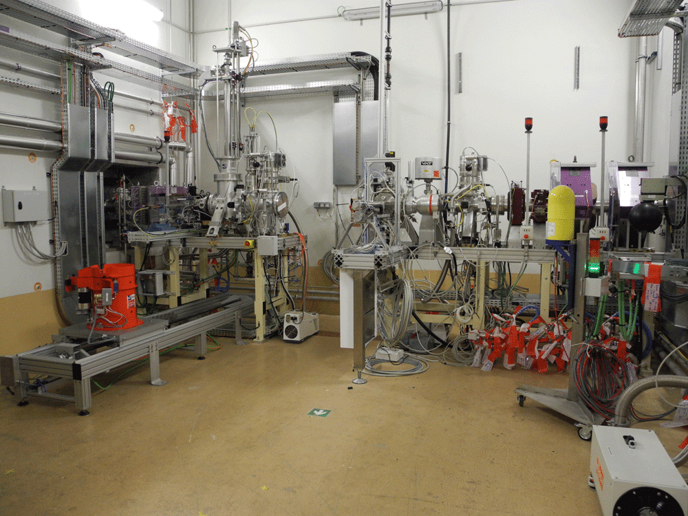
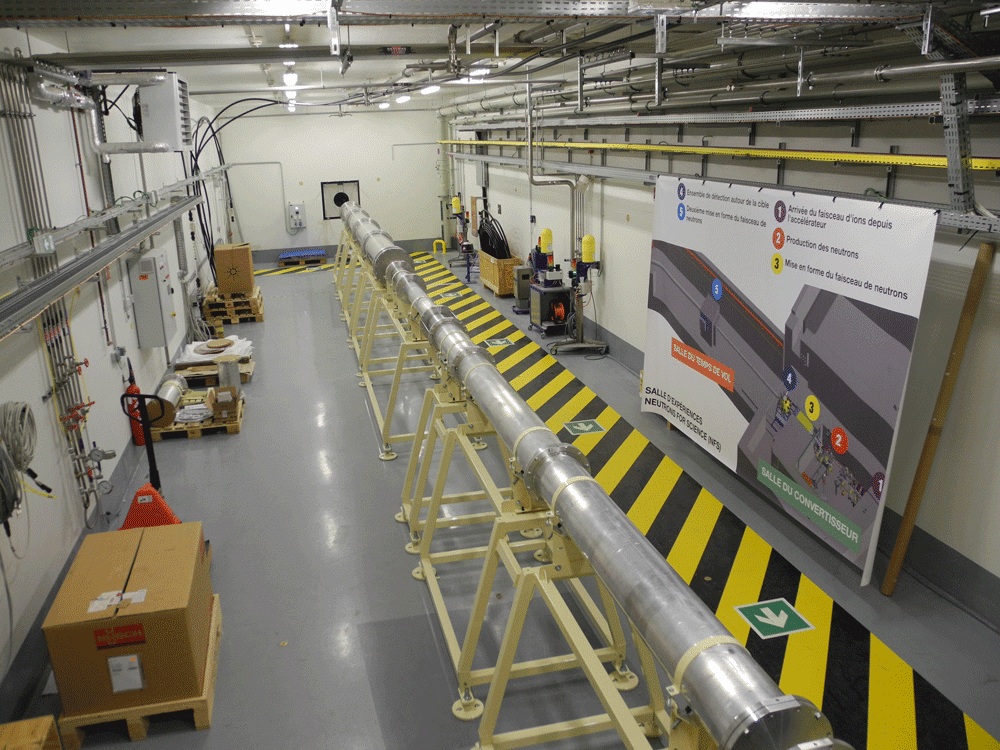
The converter cave contains the ion beam line, the converter to produce neutrons and the irradiation station for the study of ion-induced reactions. The TOF area is an experimental area of 6 m width and 30 m long allowing high-resolution energy measurements. The two rooms are separated by a 3 m thick concrete wall pierced of a hole to define the neutron beam in the TOF hall. This part is called the collimator, its design defines the neutron beam spatial extension and the neutron background in the TOF hall. A neutron beam dump is installed in the back of the TOF area in order to minimize the background induced by the neutron beam. The two rooms of NFS as well as the accelerator are undergrounded at a depth of -9.5 m.
The facility is equipped of a pneumatic system, to transfer samples from the converter room, where they are irradiated, to the TOF area to be analyzed.
In addition to neutrons induced reactions, ion induced reaction will also be studied at NFS. An irradiation station takes place in the converter room allowing the irradiation of samples by light ions delivered by the LINAG. The samples are then transferred to the TOF thank the pneumatic transfer system.
The production of neutrons
Two production modes will be used with the pulsed proton and deuteron beams delivered by the LINAG. First, the deuteron break-up reaction on a thick converter made of carbon or beryllium generates neutrons with a continuous energy distribution. At 0°, the spectrum extends up to 40 MeV with an average value of approximately 14 MeV as shown in Fig. 2. The beam is stopped in the converter and the full power is deposited in. The rotating converter has been design in order to sustain the maximum authorized power of 2000W.
Second, the 7Li(p,n)7Be reaction on a thin lithium converter (1 to 3 mm thick) produces nearly mono-energetic neutrons as shown; the neutron spectrum at 0° consists of a mono-energetic peak due to the 7Li(p,n) process and a continuum which is attributed to the break-up process. A thin converter has been designed allowing the use of lithium or beryllium converter. After crossing the lithium converter, the protons are swept out of the neutron beam by a bending magnet placed downstream of the target.
Since the primary beam frequency of the LINAG (88 MHz) is not adapted to the measurements by time-of-flight technique, a fast beam chopper will be used to reduce the frequency by a factor 100 to 10000. The maximum intensity will be then limited to 50 µA.
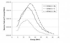
Figure 2: Neutron yield at 0° for reaction induced by deuteron on thick target [3][4]
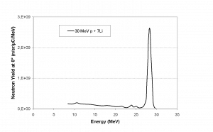
Figure 3: Neutron yield at 0° produced by Li(p,n) reaction at 30 MeV on thin converter [5]
The rotating converter
The converter design must take into account the maximum power deposition and the handling procedure after activation. A rotating converter is required to sustain the maximum power of 2 kW (40 MeV x 50 µA). It will be composed of a disk of 170 mm in diameter and 8 mm thick rotating at a speed of 2000 tr/min. Thermal calculations show that the maximum temperature will not exceed 700°C well below the melting point. After irradiation the converter being highly activated, especially due to the production of 7Be, it will be moved automatically into a lead shielding to be manipulated and replaced.
The thin converter
The production of mono-energetic neutrons requires the use of a thin (1 to 2 mm) converter of lithium or of beryllium. The low melting point of lithium (180°C) makes the cooling by radiation inefficient, thus a rotating wheel is not suitable. A fixed converter cooled by water has been studied by GANIL’s design office. Thermal calculations show that it will sustain a power of 30 µA deposited by a proton beam crossing a 2 mm thick lithium converter. The set-up is composed of 2 converters screwed on a copper plate cooled by water (see Figure 4). The converters can be remotely removed out of the beam line if the rotating converter will be used instead.
The beam characteristics
Flux
The neutron flux is estimated considering the maximum ion intensity and the neutrons yield [3] and compared to existing neutron TOF facilities around the world namely n_TOF at CERN, WNR at Los Alamos (where neutrons are produced in a spallation reaction) and GELINA in Geel (where neutrons are produced by photo-reactions). The length of the TOF area allows either high-intensity flux (5 m) or high-resolution (20 m) measurements. In order to avoid the overlap of neutrons from successive bursts, the beam repetition rate is adapted to the flight path: 1 MHz and 250 kHz for 5 and 20 m respectively. The maximum deuteron beam intensity is then 4 times lower at 20 m than at 5 m. It can be seen in Figure 5 that NFS is very competitive in terms of average flux in comparison with n_TOF, GELINA or WNR between 1 and 35 MeV. This intense average flux is due to the high beam-repetition rate, the instantaneous flux is lower than the other facilities. Moreover, NFS presents some advantages due to the neutron production mechanism itself. In spallation sources the high energy neutrons (up to hundreds MeV), may imply challenges for both collimation and background. Secondly, the gamma-flash, which is known to be very penalizing, especially because it induces dead time, will probably be strongly reduced at NFS.
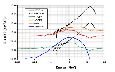
Figure 5: Comparison of the neutron flux of NFS with three other TOF facilities, WNR, n-tof and GELINA. The fluxes for NFS are shown at 5m and 20 m.
The neutron flux in the converter room very close to the converter is presented in Figure 6. By using the thick beryllium converter a flux greater than 5.1011 n/cm2/s can be reached. This very high flux can be used to measure reaction cross-sections by activation technique with small target.
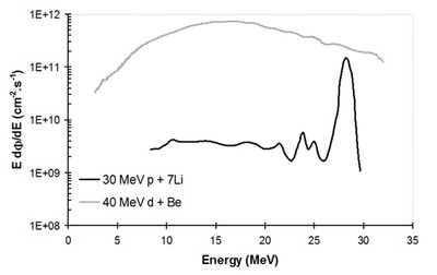
Figure 6: Neutron flux at 5 cm in front of the converter
Energy resolution
The time resolution of the ion-beam and the length of the experimental area allow the energy measurement of the incident neutrons by TOF technique with a rather good resolution. Actually the burst time spread at the converter point is estimated to be about 1 ns. The use of fast detectors (photomultipliers or silicon detectors for example with Δt ≈ 1 ns) allows to measure the energy of neutrons with a resolution better than 1% (see Figure 7). With slow detectors, like High Purity Germanium detector (Δt ≈ 8 ns), the energy resolution at 40 MeV will not be worse than 5%.
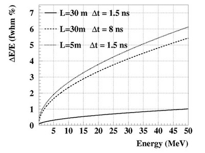
Figure 7: Energy resolution obtained with fast and slow detectors for flight path of 5 and 30 m
Beam size and background
The neutron beam characteristics and the background in the TOF area are key parameters of the NFS facility. Actually, the neutron beam must be very well collimated to interact only with the target and not hit the detection set-up surrounding the target. The background originates mainly from the collimator, the neutron beam dump and the building design. Neutron transport calculations have been realized to optimize the design of these components. All the simulations were performed with the MCNPX code version 2.5. The energy and angular distribution of the neutrons produced in the 40 MeV d + Be have been calculated using the model described in reference [7].
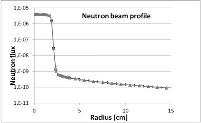
Figure 8: Neutron beam radius at 1 m from the exit of the collimator for several collimator designs
Several designs of the collimator have been studied in order to determine the best compromise between efficiency and cost. The Figure 8 shows the result of MCNPX simulations with several configurations of collimator. It can be seen that at 1 m of the exit of the collimator (approximately 5 m from the converter point) the neutron beam has a radius of 2 cm and the ratio signal over noise is around 104.
The effect of the beam-dump design optimization is illustrated in Figure 9. In the simulations the neutrons are emitted from an extended source (a disk whose diameter is equal to the diameter of the beam at the center of the beam dump). The number of neutrons backscattered to the TOF area is strongly reduced in the optimized design. The photons created by neutron interaction (n,n’),(n,g)… have also been treated and the result is presented in Figure 10. The gamma produced in converter have not been taken into account.
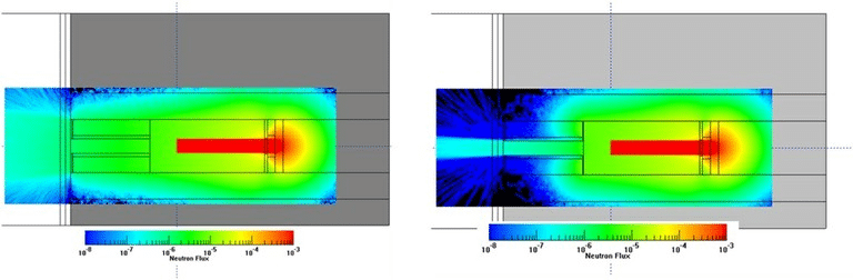
Figure 9: Neutron flux simulations (arbitrary units) in the beam dump zone, with the raw design (left) and the optimized design (right)
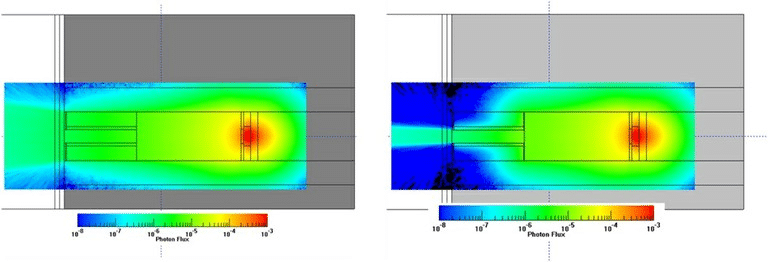
Figure 10: Photon flux simulations (arbitrary units) in the beam dump zone, with the raw design (left) and the optimized design (right)
The irradiation station
This station allows to put sample under vacuum in order to be irradiated by proton, deuteron or ions accelerated by the LINAG. It is connected to the pneumatic transfer system. The sample is fixed on a shuttle, it goes under vacuum thanks an air-lock, then the sample is put on the beam line to be irradiated. After irradiation, the sample is moved out by the air lock to the transfer system to be sent to the TOF area. The activity measured as well as the beam intensity will allow deducing the cross-section of dedicated reactions. The duration of the activation and the intensity of the beam depend on the cross-section to be measured.
The neutron-transfer system
Cross-section measurements by activation technique will also be possible at NFS. The samples will be irradiated in the convertor room and their activity measured in the TOF area with a gamma spectroscopy set-up. A pneumatic system will ensure the movement of the samples between the two rooms, the time transfer will be of approximately 1 s. For neutron-induced reactions the sample will be placed in front of the converter. The very intense available flux will permit to measure small cross-sections or to use small amount of material. For ion-induced reactions (mainly protons and deuterons), the sample will be placed under vacuum in the irradiation box placed in the beam line upstream of the converter.
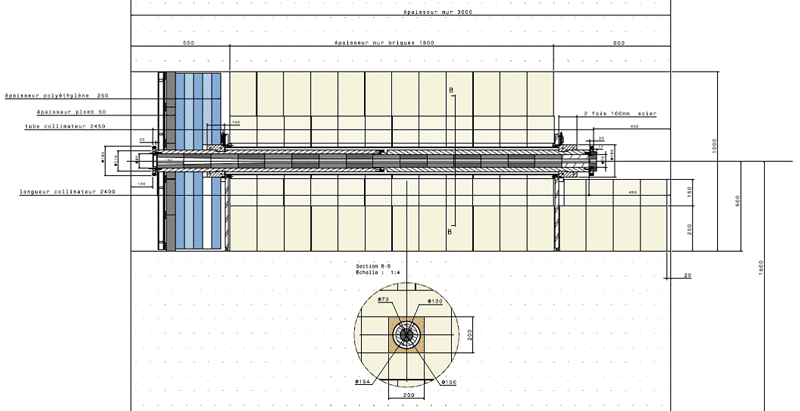
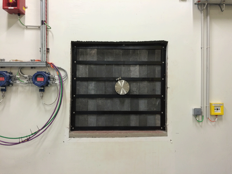
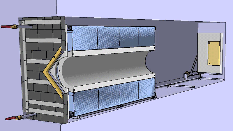
The collimator
The collimator is placed in the thick concrete wall separating the converter and the TOF rooms. The role of the collimation system is to define a well-collimated neutron beam and, therefore, its design is of special importance to the beam characteristics. The collimator will be composed of several materials arranged in ring fashion [6]. The inner part, a cylinder of iron pierced in its centre by a conical channel to define the beam, will scatter away high-energy neutrons. The outer part (in concrete and borated polyethylene) will then absorb them. Its design was studied with simulations realized with the MCNPX code[7]. Several sets of inner cylinders with different inside channel are envisaged in order to adjust the neutron beam size to the physic request.
The neutron beam dump
The neutron beam is “stopped” at the end of the TOF room in a beam dump whose design has been optimized in order to reduce the neutron backscattering to the TOF room and the gamma production. The beam dump is a hole of 4 m long and 1x1m2 of section centered on the beam axis in the concrete wall. A borated polyethylene sheet (15 cm thick) in the bottom of the hole reduces the backscattering of neutrons. A tube at the entrance of the hole (composed of borated polyethylene in the inner part and concrete in the outer part) with a diameter greater than the beam spot allows catching the neutrons and the photons.
The nominal characteristics for the call for proposal for the GANIL PAC
The nominal characteristics of NFS for the call for proposal for the GANIL PAC are the following:
Ions induced reactions:
- Protons between 0.75 MeV and 2 to 33 MeV
- Deuteron and Alpha between 0.75 MeV/u and 2 MeV/u to 20 MeV/u
Available setups:
- The irradiation station
- The sample transfer system
For neutron induced reactions:
- Quasi-mono-energetic spectrum:
- Produced by 7Li(p,n)7Be reaction on thin target
- Energy of neutrons in the peak between 5 and 30 MeV
- Maximum flux in the TOF hall of 2.105 n/s/cm2 in the peak depending on the energy and the frequency of the beam.
- Continuous spectrum:
- Produced by reaction on thick converter
- Energy spectrum extend up to 40 MeV
- Maximum flux in the TOF hall of 4.107 n/s/cm2 depending on the beam frequency
- o Maximum flux in the converter room for sample irradiation of 2.1010 n/s/cm2
Beam time structure:
- Beam frequency
- Own RFQ frequency of 88 MHz
- Reduced frequency f<880kHz
For any additional information please contact the NFS Scientific Coordinator : xavier.ledoux@ganil.fr.
Experiments requiring other characteristics can be submitted as letters of intent.